Poly Panel Roof Anchors Technical Information
Insulated Panel Systems or Composite Sandwich Panels are used in a variety of applications from industrial and commercial coolstores, to agricultural and architectural buildings, sport centres, commercial premises, warehouses and factories, offices, exhibition space, and convention centres around the world.
People can spend millions of dollars on building insulated panel coolstores to house their produce for the export market. Those products need to be kept in a controlled-temperature environment. By attaching the wrong type of height safety products or systems, you can cause damage to those insulated panels which can cost millions in export sales through loss of that controlled environment.
Metal Insulated Sandwich Panels:
The Metal Insulated Sandwich Panel is a lightweight panel system incorporating an expanded foam core with factory 0.55 gauge laminated outer steel covers in a flat or trapezoidal profile, manufactured to act as a roof system which can have a minimum pitch of 3 degrees. Unlike single skin metal roof profiles, the strength of panel construction permits exceptional spans requiring fewer structural supports.When designing any height safety anchor points or systems that are attached to Metal Insulated Sandwich Panels, extreme care must be taken to protect the core and the outer skin of the Insulated Panel from damage.
Anchor Design:
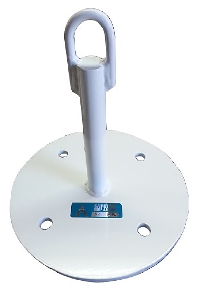
The main anchor body is made up of three components: a 10mm thick mild steel mounting plate, a 30mm mild steel stem (which can vary in height to control the type of absorption that may be required to reduce excess loading on the panel), and a 10mm diameter mild steel bar welded to the top of the stem to form the eye.
Manufacturing:
All Insulated Sandwich Panel Anchors are manufactured using 300 grade mild steel. The welding of all height safety anchors is carried out using the Welding Certification Procedure.Coatings
Plascoat PPA 571 ES is resistant to stress cracking, adverse weather conditions, detergents, salt spray and typical airborne pollutants. The coating maintains excellent adhesion to the metal substrate without the need for a separate primer. The material also provides good abrasion and impact resistance.
Protecting the Panel:
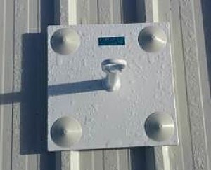
To fully protect the Insulated Panel from the dynamic force generated from a fall-arrested load, the Insulated Panel needs to be sandwiched between the main mounting plate of the height safety anchor on the outside of the building (see Photo 1), and the height safety anchor backing plate is placed on the underside of the Insulated Panel (see Photo 2).
Bonding System:
Before attaching the mounting and backing plates, we recommend applying Sikaflex 11FC white sealant to the under sides of the anchor to act as a gasket, sealant and an adhesive (see Photo 3). The bonding strength of the Sikaflex 11FC is 50kgs per 1mm square. By using both methods (bolts and Sikaflex 11FC), we are able to spread the loading over a much greater area to protect the Insulated Panel from point loading from a single bolt or fixing, which can damage the Insulated Panel.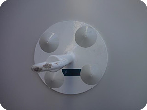
Photo 1
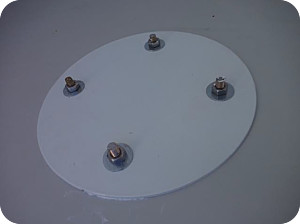
Photo 2
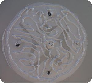
Photo 3
Bolting System:
The system we use is the same system the Insulated Panel manufactures have designed to attach the Insulated Panel to the building structure (see Dia. 1).Attachment of the anchor consists of:
- 4 x PVC tubes inserted into the core of the Insulated Panel to act as spreaders between both faces of the anchor. These stop any crushing of the Insulated Panel when the bolts are tightened.(see Dia. 1)
- Sikaflex 11FC to bond both of the anchor plates in place and to also act as a sealant and a gasket. (see Photo 3)
- 4 x 10mm threaded rods and nuts to tighten the anchor plates in place.
- 1 x 76mm mushroom head (see Photo 4). This creates a barrier between the inside and outside environments along the axis of the threaded rod.
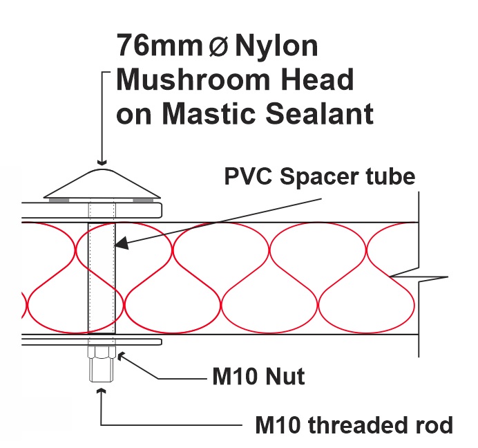
Diagram 1
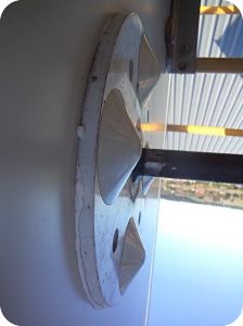
Photo 4
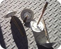
Photo 5
Testing:
1500kgs or 15kN Testing to AS/NZS 5532.2013 Standards:
All tests that were carried out on this product included a safety factor of x 2. There are two types of testing required under the AS/NZS:5532.2013 Standards for anchor points;
- When tested in accordance with the dynamic test procedure in Clause 6.3.2.2, fixed anchor devices shall not release the drop mass.
- The drop mass shall remain suspended for 3 minutes after the drop test.
- The anchor device should show no signs of fracture. Bending without signs of fracture is permissible.
- The anchor shall not release the load. Before test Photo 6. After test Photo 7.
- When tested in accordance with the static strength procedure in Clause 6.3.1.1, fixed anchor devices and the test structure to which they are attached shall sustain a force equal to their rated capacity for a period of not less than 3 minutes. The anchor device should show no signs of fracture.
- Bending without signs of fracture is permissible. Before test Photo 8. After test Photo 9.
Both the dynamic and static tests were carried out on the same panel shown in photos. Two of the same type of anchors were used for each test as allowed by the AS/NZS 5532.2013 Standards.
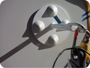
Photo 6
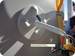
Photo 7
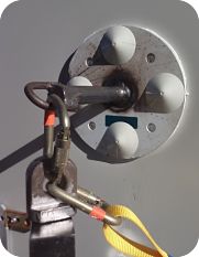
Photo 8
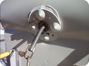
Photo 9
The panel used in both the dynamic and static tests was free standing. There were no fixings used on the top/bottom or sides of the test panel as there would be if it was attached to the structure of a building. These tests stand to replicate the worst case scenario as stated in the AS/NZS 1891.4.2009 Standards.
NB:
The maximum safe stopping force that can be placed on the human body caused by a fall is 6kN or 600kgs. Safetor Insulated Panel anchors start absorbing energy at around 3.8kN to 4kN or 380-400kgs, this brings us well under the maximum safe stopping force.
Energy Absorption:
While Safetor Mild Steel anchors yield at under 15kN or 1500kgs, it is largely due to the elasticity of the low grade mild steel we use. As the bar bends, the yield lowers because it is going through a bending process and the energy is being absorbed by the bending action. When it reaches a certain point in the bend the yield starts to rise again and well exceeds the yield for anchor points. In the strongest direction the anchor has failed at 5000kgs or 50kN and in the weakest direction the anchor has failed at 4000kgs or 40kN.
Surface Anchors on Panels
Surface Anchor Testing on Roofing Material:
There are many types of height safety surface mounted anchors designed for fall-arrest and lifelines that are in use on buildings today. These anchors are attached to roofing material using rivets, screws or bolts. The most common of these anchors are manufactured using a 4mm stainless steel mounting plate with no form of backing plate. The tests we had carried out using a riveted type system alerted us to the fact that this type of system is not safe for use as a fall-arrest anchorage device.
Point Loading on Cladding:
Point load: A load used in a testing regime as a measure of the ability of roof or wall cladding to support a person with a bag of tools, at mid span. (1.1kN)A point load is often the most severe of the imposed loads which is calculated at 112 kgs = 1.1 kN. As required by AS/NZS 1170.1 the point load is taken as 1.1 kN over an area of 100mm diameter in the case of a superimposed load, such as anchor points, the area of contact if the load is not directly attached to the structure. A point load on a roof is always positive or downward.
Roof and wall cladding is required to comply with the requirements of the NZBC clauses B1, B2, E2, E3, and also with AS/NZS 1170.
Von-Mises Stress Loading:
Von-Mises stress is considered to be a safe haven for design engineers. Using this information an engineer can say his design will fail if the maximum value of Von-Mises stress induced in the material is more than the strength of the material. This works well, especially when the material is ductile in nature.In 2015 I engaged BVT Engineering Professional Services in Christchurch New Zealand to carry out the Von-Mises stress analysis test on a surface mounted anchor. (view full report)
It was evident in the Von-Mises stress test that a 4mm stainless steel base plate has enough flexibility to direct the loading away from all the fixings, working as one to a small number of fixings depending on the direction of loading. This creates greater point loading on the sandwich panels. By using a 270mm or greater in diameter bonded anchor, manufactured from a 10mm Mild Steel plate with a 4mm backing plate that is also attached using 4 x M12 bolts, the load is then spread over a much greater area and removes point loading from the equation altogether.
Sandwich Panels Can Be Damaged By:
NB:
All lifeline or wire travel systems that are on any sandwich panel building should be removed before the sandwich panels become damaged. If a lifeline or wire travel system is to be used, the anchors should be attached to the steel structure and not just the sandwich panel.Material Testing Laboratory in Auckland New Zealand have carried out a number of static tests on roofing iron. The tests are shown below in photos 10a, 10b, and 10c. Note the roofing completely failed in photos 10b and 10c.
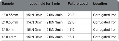
Static Test Results on Roof Material:
The static testing results on single skin roofing material are related to photos 10a,10b & 10c. The testing materials used were:The static test results do in fact show a pass on all 4 samples used, 0.55mm 21kN pass and 0.40mm 15kN pass. While the tests show a pass, we did use galvanised roofing iron which has a lower tensile strength than the more commonly used roofing material Zincalume. Corrugated roofing iron has a natural curved profile which makes it much stronger than trapezoidal roof profiles. The overall height of the test brackets riveted to the roofing was only 4mm thick (This plays a big part in any test results of this nature).
Load Transference:
Static test photos 10b and 10c show that the roofing iron failed at the last rivet. In the dynamic testing, the surface mounted anchors again failed at the last rivet as seen in photos 11b and 11c. Failure always occurs at the very last rivet because the bulk of the loading is transferred to the end rivet. Because a hole has been drilled in the roofing iron to accommodate the rivets, this creates a weak point in the roofing iron where the tearing of the material begins.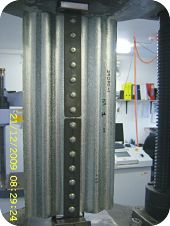
Photo 10a
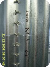
Photo 10b
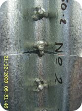
Photo 10c
Dynamic testing to 15kN as per the AS/NZS 5532.2013 Standard was carried out on the surface mounted anchor shown in the photos 11b and 12b below. The anchor failed the test. The reason this type of anchor fails is entirely due to the thickness of the mounting plate. Refer: Von-Mises stress analysis test.
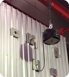
Photo 11a
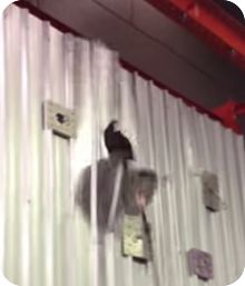
Photo 11b
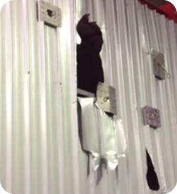
Photo 11c
Lifeline Systems:
Extreme care must be taken when attaching lifeline systems to Insulated Panel Systems or Composite Sandwich Panels which are used on coolstore buildings. By installing the wrong type of anchor systems onto Insulated Panel Systems or Composite Sandwich Panels for a lifeline system, the panels can become damaged. The poly panel can be damaged at the anchor attachment point in one of two ways.The first is wind loading on the cable. Drag on the cable caused by wind loading can put increased pressure on the cable which in turn will transfer the loading to the base of the anchor where it is attached to the poly panel. The taller the anchor the greater the force becomes at the attachment point of the anchor.
The second is loading force caused by pulling the shuttle device that connects the lanyard to the lifeline cable. The cable can have load tension placed on it as a person travels along the lifeline system. This can place a working load on the end or change of direction anchors, again creating a load on the anchor attachment point.
For safety reasons, all testing of height safety anchors should be carried out by an independent IANZ Accredited Height Safety Laboratory, which is why we engaged the services of both Telarc registered Material Testing Laboratory & QSI who are qualified to carry out AS/NZS 5532.2013 anchor testing standards.